

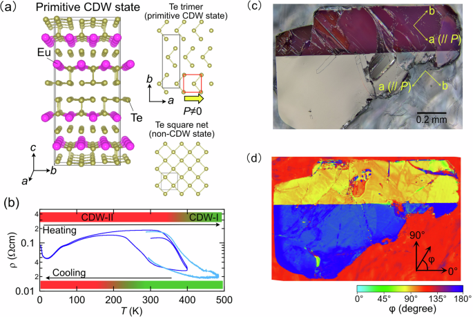
At room temperature, EuTe4 stabilises a CDW state (Fig. 1a). The lattice parameters of the CDW state are tripled along the b axis and doubled along the c axis relative to the putative non-CDW state (see Fig. S1 in Supplementary Information). Here, we denote this state as “primitive CDW state” as the actual structure has been found to exhibit higher-order modulations. Electrical transport measurements show a pronounced hysteresis near room temperature, indicative of a thermal evolution between distinct high- and low-temperature CDW phases (Fig. 1b)39. In the high-temperature phase (CDW-I), X-ray diffraction reveals incommensurate superlattice reflections characterised by modulation vector q∼0.67b∗39,40. Upon cooling, additional reflections emerge that are attributable to a low-temperature CDW phase (CDW-II)38. High-resolution synchrotron X-ray diffraction further suggests that the large hysteresis arises from a moiré-like superstructure produced by the coexistence of two incommensurate modulations with q∼0.67b∗41,42. In both phases, a subset of Te sites within the two-dimensional Te square-net layers displaces to form trimers (Fig. 1a), breaking in-plane inversion symmetry and generating an in-plane polar structure. The accompanying reduction of crystallographic symmetry from tetragonal to orthorhombic, with inequivalent a and b axes, naturally leads to the formation of orthorhombic domains. Although CDW-I and CDW-II exhibit incommensurate modulations, their essential structural motif—the Te-trimer formation and the associated inversion-symmetry breaking—is well captured by the primitive CDW state. In the following, we adopt this primitive CDW description as the basis for discussing the mechanically induced reconfiguration of CDW-coupled polar/structural domains.
Figure 1c shows a polarised-light micrograph of a EuTe4 single crystal, revealing two domains with sharply bifurcated contrast. The domains are related by ~90° rotation of the crystallographic a and b axes. Complementary two-dimensional birefringence mapping in reflection (Fig. 1d) visualises the optical principal axis as a vector field arising from the in-plane anisotropy. This map resolves two domains whose principal-axis orientations differ by ∼90°, consistent with the polarised-light image and with orthorhombic twinning. These observations establish that EuTe4 forms well-defined domains within the ab plane as a consequence of its orthorhombic symmetry. Moreover, the crystal further exhibits an in-plane polar structure with broken inversion symmetry; in the insulating limit, this axis would host a spontaneous polarisation.
To clarify the orientation of the polarisation, we performed SHG measurements in a reflection geometry (Fig. 2a). Since SHG is extremely sensitive to inversion-symmetry breaking43, it enables the detection of polarisation even in highly conductive polar materials44. For the stripe-like domains (Fig. 2d), we recorded the angular dependence of the SHG intensity (Fig. 2c) and used the maxima to extract the in-plane polarisation vector. Figure 2b presents a two-dimensional SHG intensity map acquired with the incident fundamental (ω) and emitted second-harmonic (2ω) polarisations set parallel, revealing contrast modulation along the stripe direction. The corresponding polarisation vectors (yellow arrows in Fig. 2b) are oriented at ~45° with respect to the stripe direction and rotate by about 90° between adjacent domains. These features are characteristic of the 90° polar domain topology commonly observed in in-plane-polarised two-dimensional ferroelectrics with tetragonal or pseudo-tetragonal symmetry17,45, indicating that an analogous domain structure is realised in EuTe4 (see Fig. S2 in Supplementary Information for a schematic of the polarisation and domain configuration). Note that although EuTe4 is orthorhombic, the a and b lattice parameters are sufficiently close that it can be regarded as pseudo-tetragonal for describing the in-plane polar domain topology.
From the above results, we conclude that EuTe4 hosts a domain structure with an in-plane polarisation vector. This, in turn, suggests that local mechanical fields could be used to reconfigure the polar-domain orientation. To test this possibility, we applied localised strain by gently indenting the crystal surface with a needle of ~1 µm apex radius and monitored the ensuing domain evolution using polarised-light microscopy. Preliminary tests using needles with different apex radii showed that the ~1 µm-apex-radius needle was most suitable for inducing wedge-shaped birefringence contrast under the present manual indentation conditions (Supplementary Fig. S3). The experimental arrangement is shown in Fig. 3a, b: the crystal was affixed to a glass slide with a fluorinated adhesive (CYTOP, AGC), the tip was brought into contact from above, and the process was recorded in situ (see Supplementary Video 1). We also confirmed that similar mechanically induced birefringence contrast changes were observed when EuTe4 crystals were mounted on a rigid copper plate or a softer Kapton tape, indicating that the response is not governed solely by the macroscopic substrate stiffness (Supplementary Fig. S4). Following indentation (Fig. 3c), a wedge-shaped region nucleates from the contact point with optical contrast distinct from the surrounding matrix; its mean width is ~1 µm, and its mean length is ~7 µm, as determined from the statistical analysis of 29 wedge-shaped regions described in Supplementary Fig. S5. The observed contrast indicates a large change in the local optical-axis orientation between adjacent domains, consistent with strain-induced reconfiguration of the orthorhombic (pseudo-tetragonal) CDW-coupled polar/structural domains. To examine whether this contrast arises from irreversible surface damage, we performed SEM observations on the mechanically modified regions. No clear cracks, scratches, or permanent surface deformation were observed in most wedge-shaped reconfigured regions (see Supplementary Fig. S6), indicating that the modified optical contrast is not simply a topographic artefact caused by macroscopic surface deformation.
To examine the write/erase-like response, we applied local strain near the previously written wedge-shaped domain and tracked the subsequent change in birefringence contrast using polarised-light microscopy (see Supplementary Video 2 for the indentation sequence). Figure 3d shows the image after the second indentation. Focusing on the domain marked by the yellow arrow in Fig. 3c, we find that this domain contrast is suppressed upon the second indentation, while a new domain (green arrow) appears in its vicinity. The write/erase-like contrast change occurred on the timescale of the manual mechanical operation, typically on the order of seconds, which should be regarded as an upper bound limited by the manipulation and imaging conditions rather than the intrinsic domain dynamics. These observations indicate that local mechanical stimulation can induce, suppress, or redistribute CDW-induced polar-domain contrast. The selective suppression of the domain contrast near the second indentation site, while more distant domains remain largely unchanged, likely reflects the highly nonuniform mechanical fields generated by local indentation, which decay away from the contact region. This write/erase-like response highlights the potential of local mechanical stimulation for modifying CDW-induced polar-domain states in EuTe4.
Figure 4a shows the birefringence map acquired in the same field of view as Fig. 3d. A clear rotation of the optical principal axis, shown by the colour plot of the orientation angle φ, within the wedge-shaped region is observed relative to the surrounding matrix. An enlarged view of the area exhibiting the largest domain change (black box) is presented in Fig. 4b. To quantify the spatial evolution of the principal-axis orientation within the wedge domain, Fig. 4c plots line scans along the three trajectories (I–III) indicated in Fig. 4b. In particular, along line I, the principal-axis angle varies strongly inside the wedge, and the magnitude of this variation decays gradually with distance from the indentation point. The maximum change in φ reaches approximately 60°, indicating a substantial local modification of the optical anisotropy. Because the optical anisotropy in EuTe4 is associated with the CDW-coupled polar/structural distortion, this large local change strongly suggests that the axis orientation of the CDW-coupled polar/structural domain is modified by local mechanical strain. Optical-axis analysis over a wider field of view, including regions outside the wedge-shaped feature, also shows that the wedge-shaped region exhibits a significantly larger φ change than nearby deformation-related contrast features (Supplementary Fig. S7). SHG microscopy after indentation shows a clear polarisation-dependent contrast in the wedge-like region (Supplementary Fig. S8). When both the incident fundamental light and detected SHG light are polarised parallel to the crystallographic b axis, the wedge-like region is relatively bright compared with the surrounding matrix. In contrast, when both polarisations are parallel to the crystallographic a axis, the contrast is reversed. This reversal of the SHG contrast indicates that the nonlinear optical response associated with the polar structure is modified in the mechanically reconfigured region, supporting reconfiguration of CDW-coupled polar/structural domains.
To further examine whether the mechanically induced birefringence patterns are related to the local mechanical-field geometry, we performed additional experiments with different needle orientations relative to the crystallographic axes, different needle inclination angles relative to the ab plane, and mechanical scanning along different in-plane directions. Representative results are shown in Fig. 5, with more detailed images provided in Supplementary Figs. S9 and S10. The resulting wedge-like or line-like birefringence contrast was not random, but depended on the needle orientation, contact geometry, and scanning direction. When the needle direction was varied with respect to the a and b axes, the reconfigured regions consistently appeared along directions approximately 45° from the crystallographic a and b axes, indicating that the mechanically induced reconfiguration is strongly constrained by the crystallographic anisotropy of the CDW-coupled polar/structural domains. Changing the needle inclination angle α also modified the spatial extent of the contrast features: at smaller inclination angles relative to the ab plane, the line-like or wedge-like domains tended to extend over longer distances. In addition, when the needle was mechanically scanned approximately along the a axis, wedge-like domains preferentially formed in the forward direction of the needle motion, whereas scanning approximately along the b axis produced less well-defined and more spatially broad contrast changes near the scanned regions. These crystallographic and scanning-direction dependences provide evidence that the mechanically induced domain reconfiguration is consistent with possible contributions from local anisotropic strain/stress fields and local strain-gradient fields determined by the contact geometry and needle motion. We also examined the effect of CDW thermal history by performing indentation experiments after heating the sample to 403 K and after cooling it to 81 K, followed by measurements at room temperature (Supplementary Fig. S11). Similar line-like or wedge-like birefringence contrast changes were observed in both cases, suggesting that the mechanically induced reconfiguration can occur in both CDW-I- and CDW-II-related thermal histories and is primarily associated with the in-plane Te-trimer distortion.
We now discuss the correspondence between the observed domain behaviour and the crystal structure of EuTe4. As shown in Fig. 1a, the two-dimensional Te layers form a square net; within each unit (red box), the central Te atom is displaced by ~0.2 Å along the a axis, forming a trimer. This displacement breaks in-plane inversion symmetry and stabilises an orthorhombic CDW state, defining an in-plane polarity oriented along the a axis. The observed 90° domains can be understood as neighbouring CDW-coupled polar/structural variants whose Te-trimer displacement directions are rotated by 90° with respect to each other. In this picture, the domain wall is expected to run ~45° from the Te-displacement, or polar-distortion, direction, as schematically shown in Fig. 6a. This is consistent with the domain-wall orientations observed in polarised-light microscopy and with the in-plane polar-axis directions inferred from SHG measurements. We therefore attribute the 90° domain structure in EuTe4 to the coexistence of regions with orthogonal Te-displacement directions in the square-net Te layer.
Figure 6b schematically summarises the possible relationship between Te displacement, CDW stability, and local mechanical deformation. In the putative non-CDW state with tetragonal symmetry, the Te atom resides at the centre of the square lattice. In the CDW state, by contrast, Te atoms are displaced in-plane to form Te trimers, producing a CDW-induced polar structural distortion. First-principles calculations yield a relative energy difference (enthalpy difference) of ΔH ≡ HCDW−Hnon ~ −0.0164 eV/f.u. in the absence of strain, indicating that the CDW structure with Te trimers is energetically favoured over the undistorted phase. We emphasise that ΔH represents the relative stability of the CDW and non-CDW structures and should not be regarded as an activation barrier for switching between two 90°-rotated polar-domain variants. In the absence of local strain, the two in-plane Te-displacement directions are crystallographically equivalent and energetically degenerate, as schematically shown in the left panel of Fig. 6b. When local strain is applied using a sharp tip, however, the induced strain field can be highly anisotropic. In the CDW phase of EuTe4, the Te displacement along the a axis makes the crystallographic a and b axes inequivalent, with the a axis being shorter than the b axis (3a < b). Therefore, anisotropic strain or stress is expected to modify the relative stability of CDW-coupled polar/structural variants. To examine this effect, we performed first-principles calculations under two types of anisotropic strain, effectively corresponding to tensile or compressive deformation along the a axis. The calculated results are summarised in Table 1. Tensile strain along the a axis makes ΔH more negative, changing it from −0.0164 to −0.0175 eV/f.u., indicating stabilisation of the CDW state. In contrast, compressive strain along the a axis, equivalently tensile strain along the b axis, reduces the magnitude of ΔH to −0.0145 eV/f.u., indicating destabilisation of the CDW state relative to the non-CDW structure. These results suggest that local anisotropic strain or stress can modify the relative stability of CDW-induced polar/structural states, as schematically shown in the middle panel of Fig. 6b. This strain sensitivity provides a possible microscopic basis for mechanically induced domain reconfiguration in EuTe4. Local indentation by a sharp tip is expected to generate highly nonuniform mechanical fields, including both anisotropic stress/strain and strain gradients. Therefore, the observed reconfiguration of CDW-induced polar-domain contrast may be understood in terms of at least two possible, and not mutually exclusive, mechanisms.
One possible contribution is anisotropic-stress-induced ferroelastic-like reconfiguration of CDW-coupled structural domains. In quasi-two-dimensional rare-earth tritellurides, in-plane uniaxial stress has been shown to realign the CDW ordering direction, demonstrating that CDW configurations can be strongly controlled by anisotropic strain46. This is consistent with our first-principles calculations showing that the relative stability of the CDW structure in EuTe4 is sensitive to anisotropic strain. Thus, local indentation may reconfigure the observed domain contrast by changing the relative stability of CDW-coupled polar/structural variants. At the same time, the estimated stress required to strongly destabilise the CDW state is on the order of several GPa, comparable to pressures that can induce structural damage in van der Waals crystals. Therefore, stress-induced CDW-variant selection may contribute near the tip-contact region, but it may not fully explain non-destructive reconfiguration over a wider micrometre-scale region.
Another possible contribution is a strain-gradient-induced flexoelectric bias. Local indentation can generate a radial and highly nonuniform strain-gradient field, which may produce an effective flexoelectric field near the tip (see Fig. S12 in the Supplementary Information)6,47. This field can lower the energy of CDW-induced polar/structural domains whose polar distortion, namely Te displacement, is aligned with the effective flexoelectric field, as schematically shown in the right panel of Fig. 6b. Previous studies on polar materials have shown that mechanically concentrated strain-gradient fields, such as those generated near crack or indentation regions, can induce local polar-domain responses6,15,47,48. In the present experiments, wedge-shaped reconfigured regions also emerge from the mechanically affected region near the needle contact, which is qualitatively consistent with a flexoelectric-bias scenario. In this case, the local strain-gradient field may preferentially stabilise CDW-induced polar distortions aligned with the effective flexoelectric field and thereby promote domain reconfiguration.